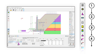
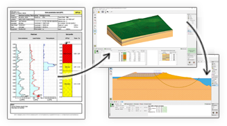
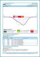
Prediction of building damage due to tunneling
Analyses performed in the program "Ground Loss" can be divided into the following groups:
The failure analysis of building is based on the shape of subsidence trough.
The analysis of subsidence trough consists of several sequential steps:
The analysis of maximum settlement and dimensions of subsidence trough can be carried out using either the theory of volume loss or the classical theories (Peck, Fazekas, Limanov).
The volume loss method is a semi-empirical method based partially on theoretical grounds. The method introduces, although indirectly, the basic parameters of excavation into the analysis (these include mechanical parameters of a medium, technological effects of excavation, excavation lining etc) using 2 comprehensive parameters (coefficient k for determination of inflection point and a percentage of volume loss VL). These parameters uniquely define the shape of subsidence trough and are determined empirically from years of experience.

Settlement expressed in terms volumes
The maximum settlement Smax, and location of inflection point Linf are provided by the following expressions:
![]()

where:
A - excavation area
Z - depth of center point of excavation
k - coefficient to calculate inflection point (material constant)
VL - percentage of volume loss
The roof deformation ua follows from:

where:
r - excavation radius
VL - percentage of volume loss
Data needed for the determination of subsidence trough using the volume loss method:
| Soil or rock | k |
|---|---|
| cohesionless soil | 0,3 |
| normaly consolidated clay | 0,5 |
| overconsolidated clay | 0,6-0,7 |
| clay slate | 0,6-0,8 |
| quartzite | 0,8-0,9 |
| Technology | VL |
|---|---|
| TBM | 0,5-1 |
| Sequential excavation method | 0,8-1,5 |
Several relationships were also derived to determine the value of lost volume VL based on stability ratio N defined by Broms and Bennermarkem:

where:
σv - verall stress along excavation axis
σt - excavation lining resistance (if lining is installed)
Sn - undrained stiffness of clay
For N < 2 the soil/rock in the vicinity of excavation is assumed elastic and stable. For N ∈ < 2,4 local plastic zones begin to develop in the vicinity of excavation, for N ∈ < 4,6 a large plastic zone develops around excavation and for N = 6 the loss of stability of tunnel face occurs. Figure shows the dependence of stability ration and lost volume VL.

Convergence analysis of an excavation and calculation of the maximum settlement in a homogeneous body are the same for all classical theories. The subsidence trough analyses then differ depending on the assumed theory (Peck, Fazekas, Limanov).
When calculating settlement the program first determines the radial loading of a circular excavation as:

where:
σz - geostatic stress in center of excavation
Kr - coefficient of pressure at rest of cohesive soil
The roof ua and the bottom ub deformations of excavation follow from:


where:
Z - depth of center point of excavation
r - excavation radius
E - modulus of elasticity of rock/soil in vicinity of excavation
ν - Poisson's number of rock/soil in vicinity of excavation
The maximum terrain settlement and the length of subsidence trough are determined as follows:

![]()
where:
Z - depth of center point of excavation
r - excavation radius
E - modulus of elasticity of rock/soil in vicinity of excavation
ν - Poisson's number of rock/soil in vicinity of excavation
When the tunnel roof displacement is prescribed the maximum settlement is provided by the following expression:

where:
Z - depth of center point of excavation
r - excavation radius
ua - tunnel roof displacement
ν - Poisson's number of rock/soil in vicinity of excavation
When determining a settlement of layered subsoil the program first calculates the settlement at the interface between the first layer above excavation and other layers of overburden Sint and determines the length of subsidence trough along layers interfaces. In this case the approach complies with the one used for a homogeneous soil.
Next (as shown in Figure) the program determines the length of subsidence trough L at the terrain surface.

Analysis of settlement for layered subsoil
The next computation differs depending on the selected analysis theory:
Limanov described the horizontal displacement above excavation with the help of lost area F:

where:
L - length of subsidence trough
F - volume loss of soil per 1 m run determined from:

where:
Lint - length of subsidence trough along interfaces above excavation
Sint - settlement of respective interface
Fazekas described the horizontal displacement above excavation using the following expression:

where:
L - length of subsidence trough
Lint - length of subsidence trough along interfaces above excavation
Sint - settlement of respective interface
Peck described the horizontal displacement above excavation using the following expression:

where:
Lint - length of subsidence trough along interfaces above excavation
Sint - settlement of respective interface
Linf - distance of inflection point of subsidence trough from excavation axis at terrain surface
The program offers two particular shapes of subsidence troughs – according to Gauss or Aversin.
A number of studies carried out both in the USA and Great Britain proved that the transverse shape of subsidence trough can be well approximated using the Gauss function. This assumption then allows us to determine the horizontal displacement at a distance x from the vertical axis of symmetry as:

where:
Si - settlement at point with coordinate xi
Smax - maximum terrain settlement
Linf - distance of inflection point
Aversin derived, based on visual inspection and measurements of underground structures in Russia, the following expression for the shape of subsidence trough:

where:
Si - settlement at point with coordinate xi
Smax - maximum terrain settlement
L - reach of subsidence trough
When the classical methods are used the inputted coefficient kinf allows the determination of the inflection point location based on Linf=L/kinf. In this case the coefficient kinf represents a very important input parameter strongly influencing the shape and slope of subsidence trough. Its value depends on the average soil or rock, respectively, in overburden – literature offers the values of kinf in the range 2,1 - 4,0.
Based on a series of FEM calculations the following values are recommended:
| gravel soil G1-G3 | kinf = 3,5 |
| sand and gravel soil S1-S5,G4,G5, rocks R5-R6 | kinf = 3,0 |
| fine-grained soil F1-F4 | kinf = 2,5 |
| fine-grained soil F5-F8 | kinf = 2,1 |
The coefficient for calculation of inflection point is inputted in the frame "Project".
The principal of superposition is used when calculating the settlement caused by structured or multiple excavations. Based on input parameters the program first determines subsidence troughs and horizontal displacements for individual excavations. The overall subsidence trough is determined subsequently.
Other variables, horizontal strain and gradient of subsidence trough, are post-processed from the overall subsidence trough.
A linear interpolation between the maximal value of the settlement Smax at a terrain surface and the displacement of roof excavation ua is used to calculate the maximum settlement S at a depth h below the terrain surface in a homogeneous body.

Analysis of subsidence trough at a depth
The width of subsidence trough at an overburden l is provided by:

where:
L - length of subsidence trough at terrain surface
r - excavation radius
Z - depth of center point
z - analysis depth
The values l and S are then used to determine the shape of subsidence trough in overburden above an excavation.
A vertical settlement is accompanied by the evolution of horizontal displacements which may cause damage to nearby buildings. The horizontal displacement can be derived from the vertical settlement providing the resulting displacement vectors are directed into the center of excavation. In such a case the horizontal displacement of the soil is provided by the following equation:

where:
x - distance of point x from axis of excavation
s(x) - settlement at point x
Z - depth of center point of excavation
The horizontal displacements are determined in a differential way along the x axis and in the transverse direction they can be expressed using the following equation:

where:
x - distance of point x from axis of excavation
s(x) - settlement at point x
Z - depth of center point of excavation
Linf - distance of inflection point
The program first determines the shape and dimensions of subsidence trough and then performs analysis of their influence on buildings.
The program offers four types of analysis:
One of the causes responsible for the damage of buildings is the horizontal tensile strain. The program highlights individual parts of a building with a color pattern that corresponds to a given class of damage. The maximum value of tensile strain is provided in the text output.
The program offers predefined zones of damage for masonry buildings. These values can be modified in the frame "Settings". Considerable experience with a number of tunnels excavated below build-up areas allowed for elaborating the relationship between the shape of subsidence trough and damage of buildings to such precision that based on this it is now possible to estimate an extent of compensations for possible damage caused by excavation with accuracy acceptable for both preparation of contractual documents and for contractors preparing proposals for excavation of tunnels.
Recommended values for masonry buildings from one to six floors are given in the following table.
| Proportional h.s. (per mille) | Damage | Description |
|---|---|---|
| 0.2 – 0.5 | Microcracks | Microcracks |
| 0.5 – 0.75 | Little damage - superficial | Cracks in plaster |
| 0.75 – 1.0 | Little damage | Small cracks in walls |
| 1.0 – 1.8 | Medium damage, functional | Cracks in walls, problems with windows and doors |
| 1.8 – | Large damage | Wide open cracks in bearing walls and beams |
One of the causes leading to the damage of buildings is the slope subsidence trough. The program highlights individual parts of a building with a color pattern that corresponds to a given class of damage. The maximum value of tensile strain is provided in the text output.
The program offers predefined zones of damage for masonry buildings. These values can be modified in the frame "Settings". Considerable experience with a number of tunnels excavated below build-up areas allowed for elaborating the relationship between the shape of subsidence trough and damage of buildings to such precision that based on this it is now possible to estimate an extent of compensations for possible damage caused by excavation with accuracy acceptable for both preparation of contractual documents and for contractors preparing proposals for excavation of tunnels.
Recommended values for masonry buildings from one to six floors are given in the following table.
| Gradient | Damage | Description |
|---|---|---|
| 1:1200 - 800 | Microcracks | Microcracks |
| 1:800 - 500 | Little damage - superficial | Cracks in plaster |
| 1:500 - 300 | Little damage | Small cracks in walls |
| 1:300 - 150 | Medium damage, functional | Cracks in walls, problems with windows and doors |
| 1:150 - 0 | Large damage | Wide open cracks in bearing walls and beams |
Definition of the term relative deflection is evident from the figure. The program searches regions on buildings with the maximum relative deflection both upwards and downwards. Clearly, from the damage of building point of view the most critical is the relative deflection upwards leading to "tensile opening" of building.

Relative deflection
Verification of the maximum relative deflection is left to the user – the following tables list the ultimate values recommended by literature.
| Type of structure |
Type of damage | Ultimate relative deflection Δ/l | |||
|---|---|---|---|---|---|
| Burland and Wroth | Meyerhof | Polshin a Tokar | ČSN 73 1001 | ||
| Unreinforced bearing walls |
Cracks in walls | For L/H = 1 - 0.0004 For L/H = 5 - 0.0008 |
0.0004 | 0.0004 | 0.0015 |
| Cracks in bearing structures | For L/H = 1 - 0.0002 For L/H = 5 - 0.0004 |
– | – | – | |
In a given section the program determines the following variables:
Evaluation of the analyzed section is left to the user – the following tables list the recommended ultimate values of relative rotation and deflection.
| Type of structure | Type of damage | Ultimate relative gradient | ||||
|---|---|---|---|---|---|---|
| Skempton | Meyerhof | Polshin a Tokar | Bjerrum | ČSN 73 1001 | ||
| Frame structures and reinforced bearing walls | Structural | 1/150 | 1/250 | 1/200 | 1/150 | |
| Cracks in walls | 1/300 | 1/500 | 1/500 | 1/500 | 1/500 | |
| Type of structure |
Type of damage | Ultimate relative deflection Δ/l | |||
|---|---|---|---|---|---|
| Burland and Wroth | Meyerhof | Polshin a Tokar | ČSN 73 1001 | ||
| Unreinforced bearing walls |
Cracks in walls | For L/H = 1 - 0.0004 For L/H = 5 - 0.0008 |
0.0004 | 0.0004 | 0.0015 |
| Cracks in bearing structures | For L/H = 1 - 0.0002 For L/H = 5 - 0.0004 |
– | – | – | |
Cracks in a masonry building due to ground movements
The author, Radko Bucek MSc., Ph.D., is a distinguished expert in the field of underground structures. He gained his abundant experience while working with world-known consultant companies such as Golder Associates, SG-Geotechnika and D2-Consult. Recently he works as the Chief Tunnel Engineer in Mott MacDonald Prague.
In cooperation with company Fine, developer of civil engineering software, the original program has been considerably improved and implemented into professional geotechnical software package GEO.
The software was used by Austrian company D2-Consult during preparation of underground line „Budapest metro line 4” in Budapest to predict ground settlement and its effects on surrounding buildings.
Since 2005 the program has been continuously used by company KO-KA for designing collectors in Prague.
Recently the software has been used by company Mott MacDonald, Prague. The author of the program works there as the chief engineer in branch of underground structures.